- The Evolution Of CubeSat Manufacturing
- Why Carbon Fiber Composite 3D Printing For CubeSats
- Design Considerations For 3D Printed CubeSat Frames
- Manufacturing Process And Material Selection
- Testing and Validation For Space Environments
- Cost And Timeline Benefits
- Future Of Additive Manufacturing In Small Satellite Development
- FAQ
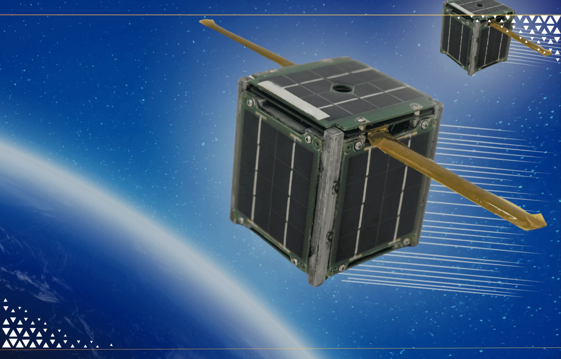
The CubeSat revolution has democratized access to space, enabling universities, startups, and research institutions to deploy orbital platforms at unprecedented scale. Yet traditional manufacturing approaches still constrain development timelines and design flexibility. 3D printed cubesat frames are fundamentally changing this equation.
Machined aluminum frames, the industry standard for years, require 8-12 week lead times and impose significant design constraints. Carbon fiber composite additive manufacturing compresses development cycles while enabling structural optimization that is impossible with subtractive methods.
Flight-proven 3D-printed cubesat implementations now orbit Earth, validating the technology for mission-critical applications, which should reassure aerospace engineers and industry professionals of its proven performance.
This article examines how aerospace engineers and research teams can leverage additive manufacturing for CubeSat frame development, from design principles through qualification testing to orbital deployment.
The Evolution Of CubeSat Manufacturing
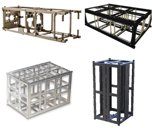
Machined aluminum dominated early CubeSat structural design for practical reasons: established aerospace heritage, known material properties, and straightforward qualification paths. However, traditional approaches impose significant limitations.
Source: NASA
Lead times of 6-12 weeks create scheduling challenges in rapid-response mission scenarios. High minimum order quantities force programs to commit to designs before integration testing reveals potential issues. Subtractive manufacturing restricts geometries to relatively simple forms; complex internal features and organic shapes remain prohibitively expensive or impossible. Each design iteration requires new tooling, adding $5,000-15,000 per change.
Weight represents another constraint. Machined parts carry material in regions where structure isn’t needed, simply because removing it costs more than leaving it. For satellites that cost $2,000-10,000 per gram to launch, these penalties compound quickly.
The Additive Manufacturing Shift
Academic laboratories began experimenting with 3d printed cubesat structures in the early 2010s, initially for ground testing and engineering models. These early efforts used standard plastics unsuitable for space environments but proved the concept of rapid, customized structural fabrication.
The breakthrough came with carbon fiber composite printing technologies, enabling space-grade material properties. According to NASA technical publications, additive manufacturing for space applications has matured significantly, with multiple missions successfully deploying 3D-printed structural components. Detailing the space durability and long-term performance of these materials addresses concerns about their reliability in harsh space environments.
Today, flight-qualified cube satellite design regularly incorporates additively manufactured frames. Regulatory bodies, including NASA and ESA, have established qualification pathways, and launch providers increasingly accept printed structures meeting standard testing requirements. Clarifying these pathways helps aerospace engineers understand how to validate and certify 3D printed CubeSat frames for mission deployment.
Why Carbon Fiber Composite 3D Printing for CubeSats
Anisoprint industrial solution PROM IS 500 makes it possible to manufacture components strong enough to resist high overloads to get through the gravity well and also thermally resistant, for operating in the open space environment with a temperature range ±150 °C. This is why a high temperature plastic (PEEK) was chosen for the case. In contrast, non-engineering plastics may have a working temperature range around –50 °C/ +100 °C which is suitable for applications on earth.
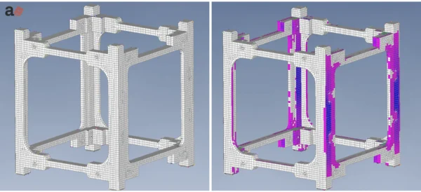
Specific stiffness of the frame was estimated using modal analysis. Natural frequency of the equivalent aluminum frame was taken as reference value for design. FEA has been applied to conduct a modal analysis.
Superior Strength-to-Weight Ratio
Carbon fiber composites deliver 40-50% weight savings compared to 6061-T6 aluminum while maintaining comparable structural performance. For a 3U CubeSat, this translates to 40-70 grams saved—mass that can be allocated to payload or additional batteries.
Launch costs make this significant. At $5,000 per kilogram to low Earth orbit (LEO) on rideshare missions, that 50-gram reduction represents $250 in direct launch cost savings per satellite. For constellation deployments of 50+ satellites, the economics become compelling.
Structural performance matches mission requirements. Properly designed carbon fiber cubesat frames withstand the same quasi-static loads (typically 8-14 G) and random vibration environments (14.1 Grms) as aluminum equivalents. The key lies in fiber orientation—aligning continuous reinforcement with primary load paths.
Design Freedom for Complex Geometries
Additive manufacturing enables cube satellite design features that are impossible or impractical with machining. Integrated mounting bosses eliminate the need for separate brackets and fasteners. Topology-optimized structures place material only where stress analysis indicates it’s needed. Internal cable routing channels guide harnesses without external clips or tie-downs.
Complex geometries that would require multi-axis machining and multiple setups print as single components. This consolidation reduces part count, eliminates assembly operations, and removes potential failure points from mechanical interfaces.
Thermal Management Integration
Carbon fiber’s anisotropic properties enable thermal engineering at the structural level. Fiber orientation controls the coefficient of thermal expansion (CTE), allowing designers to tune dimensional stability for specific thermal environments. This matters when managing extreme temperature cycling from -150°C in shadow to +150°C in direct sunlight.
Integrated thermal pathways—channels or features within the structure—route heat from concentrated sources to radiating surfaces. These features integrate during printing rather than requiring secondary machining or added components.
Rapid Iteration and Customization
Mission-specific requirements often emerge during integration testing. Traditional manufacturing makes design changes expensive and time-consuming. 3d printed cubesat approaches implement modifications overnight by updating digital files and reprinting.
Constellation programs deploying multiple satellites benefit from rapid customization. Each satellite carries different payload configurations requiring structural variations. Additive manufacturing produces these variants without retooling costs or setup time.
Design Considerations for 3D Printed CubeSat Frames
Structural Requirements and Standards
The CubeSat Design Specification (CDS) establishes dimensional and interface requirements. Cubesat dispenser compatibility demands precise rail dimensions (typically 8.5mm square rails with ±0.1mm tolerances) and specific surface finishes to ensure reliable deployment.
Launch vehicle load cases drive structural design. Quasi-static acceleration, random vibration, and shock environments vary by launch provider but typically envelope 14.1 Grms random vibration and 8-14 G quasi-static loads. Designers apply factors of safety (commonly 1.25-1.5 for flight hardware), ensuring an adequate margin.
Interface tolerances require careful attention. Post-processing operations, machining, or grinding, bring critical surfaces to specification after printing. Rail parallelism, perpendicularity, and surface roughness all affect deployment reliability from P-POD, NLAS, or other standard dispensers.
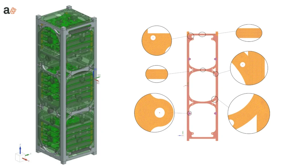
Fiber Orientation Strategy
Continuous fiber reinforcement provides maximum strength when aligned with load paths. Layer-by-layer orientation planning ensures fibers run parallel to tensile loads and perpendicular to surfaces experiencing peel stresses.
Balancing stiffness in multiple axes prevents an asymmetric response to vibration environments. A pure unidirectional layup creates strong parts in one direction but weak in others. Quasi-isotropic layups (alternating 0°, 45°, 90°, -45°) provide more balanced properties at a slight weight penalty.
Critical interfaces, launch vehicle attachment points, payload mounting surfaces—receive additional fiber reinforcement. These regions experience concentrated loads requiring local strength increases beyond the baseline structure.
Mass Budget Optimization
Topology optimization software identifies material distribution to minimize mass under specified load cases. These algorithms remove material from low-stress regions while reinforcing high-stress areas, creating organic structures resembling natural forms like bones or plant stems.
Generative design workflows iterate thousands of configurations, evaluating each against mass and performance targets. The resulting geometries often surprise engineers but deliver validated performance at minimum weight.
The reserve mass allocation (typically 10-15% of the structure budget) accommodates design changes during integration. This margin prevents last-minute compromises when unexpected requirements emerge.
Manufacturing Process And Material Selection
Carbon Fiber Composite Technologies
Several additive processes produce space-grade carbon fiber structures. Continuous fiber fabrication (CFF) embeds unbroken carbon fiber tows during printing, achieving the highest strength-to-weight ratios. Fiber-reinforced FDM blends chopped carbon fibers with thermoplastic matrix materials, offering easier processing at a slight performance penalty.
Material selection balances performance against processing requirements. Carbon fiber-reinforced polyamide (PA/CF) offers good mechanical properties at moderate processing temperatures. PEEK/CF offers higher temperature resistance for hot structures but requires sophisticated thermal management during printing. PEI/CF splits the difference, combining good properties with reasonable processing demands.
Print Parameters for Space-Grade Quality
Void content directly impacts structural performance. Space-grade components target less than 2% voids through careful temperature control, appropriate print speeds, and optimized layer compression. Too fast, and layers don’t bond properly; too slow, and thermal gradients cause warping.
Fiber volume fraction, the percentage of composite volume occupied by reinforcement versus matrix, typically runs 30-50% for optimal properties. Lower fractions underutilize the carbon fiber’s strength; higher fractions create processing challenges and brittle behavior.
Post-processing includes thermal post-cure cycles, strengthening matrix materials, and surface-finishing operations that bring interfaces to specification. CNC machining of critical surfaces after printing ensures dimensional accuracy where it matters most.
Quality Assurance During Manufacturing
In-process monitoring catches defects during printing rather than after completion. Thermal imaging tracks temperature profiles, ensuring consistent layer bonding. Some systems include optical verification of fiber placement, confirming that continuous filaments run where design files specify.
CT scanning provides a non-destructive evaluation of internal structure. These high-resolution 3D images reveal voids, fiber misalignment, and other defects that are invisible to external inspection. Critical flight hardware receives 100% CT inspection; non-critical components may use sampling approaches.
For programs requiring metal components integrated with composite structures, Additive Plus’s DMLS services provide precision metal inserts, brackets, and interfaces. Hybrid approaches, 3D printed composite primary structure with metal reinforcements at high-load interfaces, optimize each material’s strengths.
Testing and Validation for Space Environments
Mechanical Testing Requirements
Quasi-static load testing applies forces simulating launch acceleration in multiple axes. Test fixtures mount the CubeSat frame as it would be installed in the CubeSat dispenser, then hydraulic or mechanical systems apply loads to qualification levels (typically 1.25-1.5× flight levels).
Random vibration testing subjects hardware to broad-spectrum mechanical energy matching launch vehicle environments. Shaker tables generate specified power spectral density profiles while accelerometers monitor structural response. Successful testing shows no resonances in restricted frequency bands and no structural damage.
Shock testing simulates separation events, pyrotechnic release from dispensers or deployment mechanisms firing. These high-amplitude, short-duration pulses can exceed 100 G in some axes.
Environmental Testing
Thermal vacuum (TVAC) chambers cycle hardware through temperature extremes while maintaining space-equivalent vacuum. Multiple cycles (-150°C to +150°C are standard for LEO missions to verify structural integrity and dimensional stability through thermal expansion/contraction.
Atomic oxygen (AO) resistance matters for LEO missions below 700km altitude. Ground testing exposes materials to AO plasma simulating years of orbital exposure. Carbon fiber composites generally resist AO well, though surface erosion rates require characterization.
Outgassing testing per NASA ASTM E595 quantifies total mass loss (TML) and collected volatile condensable material (CVCM). Space-grade materials must meet specified limits to prevent contamination of sensitive surfaces, such as optics or solar cells.
Research published in aerospace engineering journals demonstrates that carbon fiber composites can meet these environmental requirements when properly selected and processed.
Qualification vs. Acceptance Testing
Most CubeSat programs follow protoflight test approaches: they build one structural unit that undergoes qualification-level testing, then fly it as flight hardware. This reduces program costs versus separate qualification and flight units but requires high confidence in manufacturing consistency.
Documentation for launch providers includes test reports, material certifications, and structural analysis. The manufacturing method (additive vs. subtractive) matters less than demonstrated performance meeting requirements.
Cost and Timeline Benefits
Traditional vs. Additive Manufacturing Comparison
| Aspect | Traditional Machining | 3D Printed CubeSat |
| Lead Time | 8-12 weeks | 1-2 weeks |
| Design Iteration Cost | $5,000-15,000 | $500-2,000 |
| Minimum Quantity | Often 5-10 units | 1 unit |
| Customization Cost | High (new tooling) | Minimal (file change) |
| Weight (1U frame) | 120-150g | 70-100g |
CFRPs (Continuous Fiber Reinforced Polymers) have a pronounced anisotropy of properties, which manifests itself in a high modulus of elasticity along the fibers, and low in transverse directions, as well as a low shear modulus. From this point, proper material orientation is very important for structural application. Anisoprinting gives us freedom of fiber placement, while the TO (Topology Optimization) helps us to get rid of ineffective material zones.
Total Program Cost Impact
Development cycle compression represents the largest cost benefit. Programs deploying satellites 6-12 months faster capture market opportunities, meet launch windows, or respond to emerging requirements that would otherwise require new procurement cycles.
Launch cost savings from weight reduction accumulate across constellations. A 50-satellite constellation saving 50 grams per satellite eliminates 2.5 kilograms from launch mass—worth $12,500-25,000 depending on launch provider.
Eliminated tooling costs matter most for programs with design evolution. Each iteration avoiding $10,000 in machining setup and tooling represents pure savings. Programs typically iterate 3-5 times during development, making this substantial.
Future Of Additive Manufacturing In Small Satellite Development
The trajectory of 3d printing in space points toward on-orbit manufacturing capabilities. International Space Station experiments have demonstrated polymer printing in microgravity. Future systems may fabricate structural components in orbit, enabling in-space assembly of larger structures from additively manufactured components.
Material development continues to advance space-grade composite formulations. New fiber types, matrix materials, and hybrid approaches expand the performance envelope available to satellite designers.
Integrated electronics printing, embedding conductors, sensors, and simple circuits within structural materials, could eliminate traditional harnesses and create truly multifunctional structures. These structural electronics are still in research phases but show promise for future 3D printing in space applications.
Scaling beyond CubeSats to ESPA-class and larger platforms extends the impact of additive manufacturing. The same benefits, rapid iteration, mass optimization, and design freedom, apply at larger scales with proportionally greater cost savings.
Regulatory evolution will continue supporting additive manufacturing as flight heritage accumulates and qualification databases mature. What began as experimental approaches is becoming standard practice for the NewSpace industry.
Exploring additive manufacturing for your satellite program?
Additive Plus’s DMLS services provide precision metal components that integrate seamlessly with composite structures.
Contact our aerospace manufacturing team to discuss how advanced 3D printing capabilities can accelerate your CubeSat development timeline, reduce costs, and optimize structural performance for your specific mission requirements.
Contact a Specialist
FAQ
Are 3D-printed CubeSat frames as strong as traditional aluminum structures?
Yes, when appropriately designed. Carbon fiber composite cubesat frames achieve comparable or superior strength-to-weight ratios versus aluminum. Continuous fiber reinforcement provides directional strength that exceeds that of aluminum in primary load paths. Proper fiber orientation and testing validation ensure structural performance.
What materials are approved for flight CubeSat applications?
Carbon fiber reinforced polyamide (PA/CF) and PEEK/CF are the most common for 3d printed cubesat structures. Material qualification requires outgassing testing (NASA ASTM E595), thermal cycling, and mechanical testing. Several carbon fiber composites have flight heritage on successful missions.
How does the cost of a 3D-printed frame compare to machined aluminum?
Initial unit costs are comparable ($2,000- $ 5,000 for a 3U frame). Savings come from eliminated tooling costs ($10,000-30,000), faster iterations, and reduced lead times. For programs with design changes or multiple variants, cubeSat 3D-printing approaches save 40-60% on total development costs.
Can 3D printed frames meet CubeSat dispenser interface requirements?
Yes. Post-processing achieves required rail tolerances (±0.1mm typical). Surface finishing brings rail friction coefficients within CubeSat dispenser specifications. Many flight-proven examples demonstrate successful deployment from P-POD and other standard dispensers with printed frames.
What’s the typical lead time for a 3D printed CubeSat frame?
Design to finished part: 1-2 weeks for initial prototypes, 2-4 weeks for flight-qualified units, including testing. Traditional machining requires 8-12 weeks. For constellation programs, 3D-printed cubesat production scales to multiple units per week once the design is validated.
Do launch providers accept 3D printed structures?
Increasingly yes. Launch providers require structural test data regardless of manufacturing method. 3D-printed cubesat frames that meet qualification testing requirements are accepted by major launch providers. Documentation and test reports follow the same requirements as traditional structures.
Frequently asked questions
Why use carbon fiber composite 3D printing for CubeSat frames?
Carbon fiber composites deliver 40-50% weight savings versus 6061-T6 aluminum while matching structural performance. For a 3U CubeSat that saves 40-70 grams, and at roughly $5,000 per kilogram to low Earth orbit a 50-gram reduction cuts about $250 in launch cost per satellite - economics that compound across large constellations.
How much faster is 3D printing CubeSat frames than machining aluminum?
Additive manufacturing compresses development cycles that machined aluminum stretches to 6-12 week lead times. Machined frames also carry high minimum order quantities and add $5,000-15,000 per design change for new tooling, while printed frames allow rapid, customized iteration without retooling between revisions.
What material handles the temperature range of open space for CubeSats?
PEEK, a high-temperature engineering plastic, was chosen for the case because open space spans a temperature range of plus or minus 150 degrees C. Non-engineering plastics typically work only around minus 50 to plus 100 degrees C, suitable for Earth applications but not the thermal extremes of orbit.
What loads must a 3D printed CubeSat frame survive?
Properly designed carbon fiber CubeSat frames withstand the same quasi-static loads, typically 8-14 G, and random vibration environments around 14.1 Grms, as aluminum equivalents. The key is fiber orientation - aligning continuous reinforcement with the primary load paths so the printed structure meets launch qualification requirements.
What design advantages does additive manufacturing give CubeSat structures?
It enables features that are impractical to machine: integrated mounting bosses that eliminate separate brackets, topology-optimized structures that place material only where stress analysis requires it, and internal cable routing channels. Consolidating these into single printed components reduces part count, assembly operations, and potential failure points.
Which printer was used to manufacture the carbon fiber CubeSat frame?
The Anisoprint industrial system PROM IS 500 was used, producing components strong enough to survive high launch overloads and thermally resistant for open space. Specific frame stiffness was estimated using modal analysis, with the natural frequency of an equivalent aluminum frame taken as the reference and FEA applied to validate the design.
Talk to an engineer
Have a question or a project? Let’s talk.
Tell us what you need — a real applications engineer replies within 24 hours. NDA standard, no sales script.
Have a question?
Tell us about your part, material, or project. Our engineers reply within 24 hours.