Tailored Warranty And Support
Financing Available Today

3D printing software and design

Additive Plus Education

3D printing software & design — from CAD to a printable file.

Every printed part starts as a digital model. This guide walks the path from CAD to the printer: which file formats work, what an STL file really is, how to export it cleanly and how to design for printability.

How a 3D file becomes a part
Which file formats work
What an STL file really is
Exporting & optimising for print
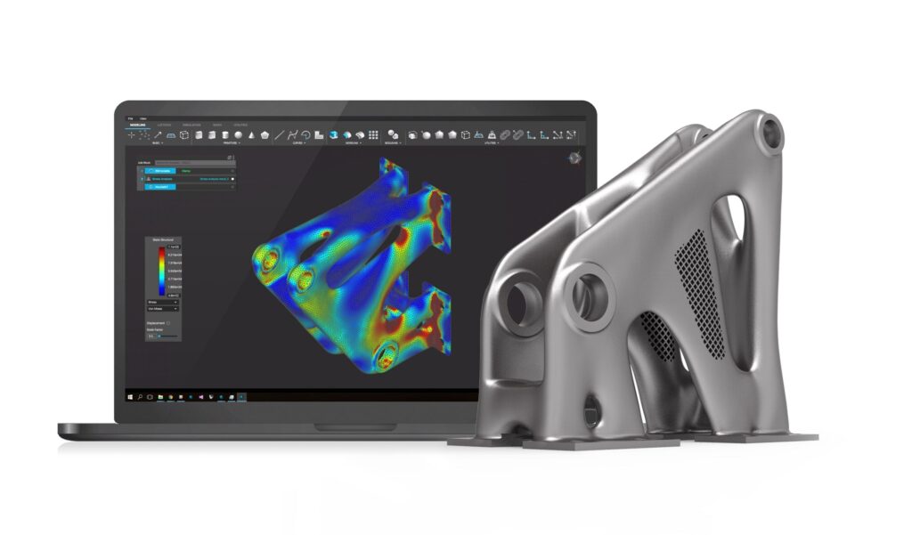
Topology-optimised bracket designed in nTopology software for metal 3D printing
Overview

Design is half the print.

In additive manufacturing, digital design is closely linked to computer numerical control (CNC): a three-dimensional model on screen becomes a physical object, layer by layer. The applications span aerospace, medical, automotive, construction and science — and reach into art, architecture, fashion and film. But a great print starts with a well-prepared file. Here is what happens between your CAD model and the machine.

Building on our Introduction to 3D Printing, in this section you will learn:

Workflow

How a 3D file becomes a 3D-printed part

The first step is a 3D file that your slicing software can read. The standard choice is often STL, but alternatives like STEP or 3MF can give better results — they carry more model information, which helps when you want smooth curves rather than coarse polygons.

Once the file is imported, the slicer generates the instructions the machine follows — usually a .gcode file for CNC-based 3D printing, though the exact extension varies by technology and brand. There are thousands of slicers, open- and closed-source, each with its own optimised algorithms. These slicing and modelling skills are essential for getting started with the technology.

Diagram of the steps from a 3D CAD model to a finished 3D-printed part
From 3D model to 3D-printed part, step by step. Image credit: IGORAZA / Medium.

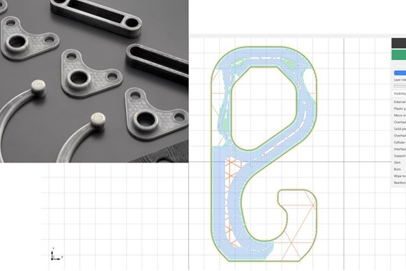
Good software does more than convert files — it can make parts stronger. In the example below, the user started from a 3D model and used the slicer to add continuous fibres, increasing the part’s anisotropy (stronger in the X and Y axes). It is a clear demonstration of what the right slicing strategy can achieve.

Anisoprint continuous-fibre slicing software adding reinforcement to a 3D model
Continuous-fibre reinforcement added in the slicer. Image credit: Anisoprint.
File formats

Which 3D files are compatible with 3D printing?

There is a great range of 3D modelling software, each tailored to different needs:

Blender

A free, open-source tool prized for its versatility, with a comprehensive feature set suitable for beginners and professionals alike.

Fusion 360

Developed by Autodesk, it stands out for seamless integration of CAD (design) and CAM (manufacturing) — an ideal choice for product design and engineering projects.

SolidWorks

A Dassault Systèmes product renowned for robust parametric modelling, giving precise control over designs and easy collaboration across teams — and many more besides.

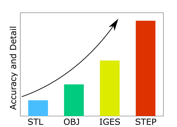
When it comes to exporting printable files, these tools typically support common formats such as STL, OBJ, 3MF, STP and STEP. Accuracy of the exported file varies with several factors: precision settings preserve dimensions and geometric detail; mesh quality — finer resolution — yields smoother surfaces and sharper edges; and model complexity means intricate designs need extra care to stay precise. In short, the software offers a range of export capabilities, but users must set the parameters to reach the accuracy they need.

Graph comparing the geometric accuracy of different 3D file extensions
Accuracy of different 3D file extensions.
STL files

What is an STL file?

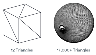
The .STL format has become the standard for sharing 3D models in the rapid-prototyping industry. It represents a solid model’s surfaces with triangles. A simple cube may need only twelve triangles — two per face. More complex shapes need many more to approximate the surface.

“Covering a surface with geometric shapes, without overlaps or gaps, is called tessellation. STL uses triangle tessellation to approximate geometries.”

Example of triangle tessellation approximating a curved surface
Triangle tessellation approximating a curved surface. Image credit: Protolabs.

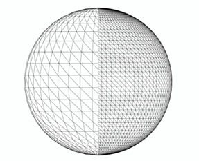
Picture a sphere. Represent it with a few large triangles and you get the rough shape; keep adding smaller, more numerous triangles and the surface gets closer and closer to a true sphere. That progressive refinement is triangle tessellation — and it is the trade-off at the heart of every STL file.

Triangle tessellation of a sphere shown as an STL mesh
Triangle tessellation of a sphere — an STL model. Image credit: FOXDOC.
Exporting

How to export your file into STL

Most modelling software can create an STL easily — usually just File → Save As → STL. A few general rules produce high-quality files:

•  Most CAD programs let you set a tolerance or chord height that controls how much fine detail is captured.

•  Tighter parameters mean more triangles on the surface — and larger files.

•  Simple designs are a few hundred kilobytes; complex models run 1–5 MB and still work well.

•  Files larger than 5 MB are rarely necessary and can slow down quoting and handling.

•  Always export as Binary for faster processing and smaller size.

These are general tips and won’t always produce the perfect file — check your software’s user guide or ask the developer for process-specific settings. The exact menu path differs by package — here are the steps for the most common CAD systems:

Pro/E

  • File → Export → Model
  • STL
  • Set chord height to 0 — the field is replaced by the minimum acceptable value
  • Set Angle Control to 1
  • OK

Pro/E Wildfire

  • File → Save a Copy → Model
  • Change type to STL (*.stl)
  • Set Chord Height to 0 (replaced by the minimum value)
  • Set Angle Control to 1
  • OK

Alibre

  • File
  • Export
  • Save As → STL
  • Enter file name
  • Save

AutoCAD (R14–2000i)

  • At the command prompt type “FACETRES”
  • Set FACETRES between 1 and 10 (1 = low, 10 = high resolution for STL triangles)
  • At the command prompt type “STLOUT”
  • Select objects
  • Choose “Y” for Binary
  • Choose filename

I-DEAS

  • File → Export → Rapid Prototype File → OK
  • Select the part to be prototyped
  • Select prototype device → SLA500.dat → OK
  • Set absolute facet deviation to 0.000395
  • Select Binary → OK

IronCAD

  • Right-click on the part
  • Part Properties → Rendering
  • Set Facet Surface Smoothing to 150
  • File → Export
  • Choose .STL

Mechanical Desktop

  • Use the AMSTLOUT command to export your STL file. The following command-line options affect quality and should be adjusted:
  • Angular Tolerance — limits the angle between the normals of adjacent triangles. Default 15°; reducing it increases resolution.
  • Aspect Ratio — controls the height/width ratio of facets. 1 means height no greater than width. Default 0 (ignored).
  • Surface Tolerance — greatest distance between a facet edge and the actual geometry. 0.0000 is ignored.
  • Vertex Spacing — controls facet edge length. Default 0.0000 (ignored).

Rhino

  • File → Save As
  • Select File Type → STL
  • Enter a name for the STL file
  • Save
  • Select Binary STL Files

SolidDesigner (v8.x)

  • File → Save
  • Select File Type → STL
  • Select Data
  • OK

Solid Edge

  • File → Save As
  • Set Save As Type to STL
  • Options
  • Set Conversion Tolerance to inches or millimetres
  • Save

SolidWorks

  • File → Save As
  • Set Save As Type to STL
  • Options → Fine → OK
  • Save

Think3

  • File → Save As
  • Set Save As Type to STL
  • Save

Unigraphics

  • File → Export → Rapid Prototyping
  • Set Output type to Binary
  • Set Triangle Tolerance to 0.0025
  • Set Adjacency Tolerance to 0.12
  • Set Auto Normal Gen to On
  • Set Normal Display to Off
  • Set Triangle Display to On

CADKey

  • Choose Stereolithography from Export options
  • Enter the filename
  • Click OK

Autodesk Inventor

  • Save Copy As
  • Select STL
  • Choose Options → set to High
  • Enter file name
  • Save

3D Studio Max

  • First check for errors — an STL object must define a complete, closed surface. Use the STL-Check modifier before export.
  • Select an object → Modify → More… → select “STL-Check” under Object-Space Modifiers → Check.
  • If there are no errors: File → Export → select “StereoLitho [*.STL]” → choose location and file name → Save → OK.
  • In the Export to STL dialog set the Object Name, choose Binary or ASCII (ASCII files are much larger), and use “Selected Only” to export just the selected objects.

ADT

  • Select the AEC object. Go to the 3D Solid menu and select Convert to 3D Solid (Enter).
  • Option “Erase selected object [Yes/No] <Yes>”: enter Y.
  • All objects are converted to 3D solid; repeat for each AEC object.
  • Select a single solid for STL output (must be ONE solid).
  • Command entry: stlout
  • Select objects and press Enter when finished.
  • “Create a binary STL file? [Yes/No] <Yes>”: enter Y.

Revit

Revit doesn’t allow direct STL export — first save as DWG and open in AutoCAD.

  • Go to a 3D view.
  • File menu → Export CAD format.
  • In the dialog, scroll the drop-down (3D view only) and select 3D polymesh.
  • Set Save As Type to “AutoCAD 2004 DWG”.
  • Open the saved file in AutoCAD.
  • Enter Explode, select the object, press Enter — all objects convert to 3D solid.
  • Select a single solid for STL output (must be ONE solid).
  • Enter stlout (or export).
  • Select objects, press Enter.
  • “Create a binary STL file? [Yes/No] <Yes>”: enter Y.

Is every STL file 3D-printable?

Unfortunately, no. Only designs specifically tailored for 3D printing — with adequate wall thickness and sound geometry — can be printed. The STL merely holds the data; it does not guarantee printability. Making sure your file meets those criteria avoids wasted time, frustration and material.

Optimising

How to optimise a 3D file for printing

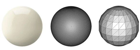
Because STL approximates a CAD model with triangles, smaller triangles give smoother parts — but bigger files. The printer reproduces exactly the coarseness stored in the STL, so the goal is to balance print quality against file size. Most CAD software exposes settings to tune triangle size for the sweet spot.

Perfect spherical surface approximated by coarse and fine triangle tessellations
The perfect sphere (left) approximated with coarse, then finer triangles — smoother on the right. Image credit: Materialise.

Chord height and tolerance

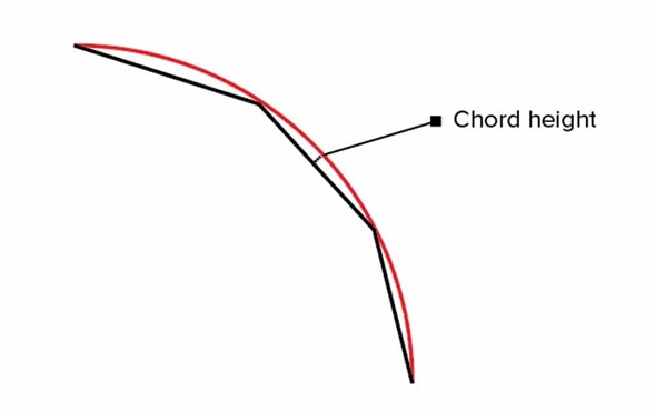
Chord height (or tolerance) sets the maximum distance between the original design surface and the STL mesh. Smaller chord heights mean the facets follow the surface more accurately, giving smooth, non-pixelated prints. Settings between 0.01 and 0.001 mm generally produce high-quality results — going finer is pointless, because the printer cannot resolve that much detail.

Diagram of chord height, the gap between the STL mesh and the actual surface
Chord height — the gap between the STL mesh and the real surface. Image credit: 3D Hubs.

Angular deviation (angular tolerance)

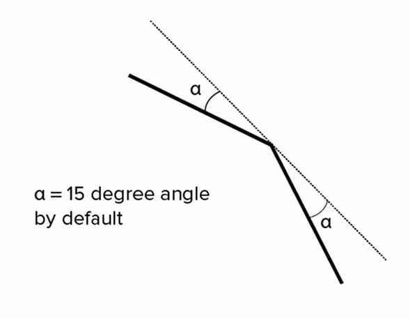
Angular tolerance limits the angle between the normals of adjacent triangles. The default is usually 15 degrees; lowering it (the range runs 0 to 1) increases resolution. As with chord height, there is a practical floor — tighten it to match your part, not beyond what the machine can print.

Diagram of angular tolerance, the angle between the normals of adjacent triangles
Angular tolerance — the angle between adjacent triangle normals. Image credit: 3D Hubs.

Binary or ASCII?

When you export an STL, binary is preferred for 3D printing thanks to its smaller file size; ASCII is easier to read for manual inspection or debugging. Beyond the software, effective design for manufacturing means understanding the advantages and limits of each process and material — tailoring geometry for post-processing, tolerances and resolution is what delivers the best results.

Ready to print a design? See which materials fit your part in our 3D printing materials guide, or browse the materials catalogue →

Curious about 3D models and design? Let’s talk.

There’s always more to discover. Reach out for an insightful conversation about designing for 3D printing — and watch for our upcoming webinars, where we explore the technology in depth.