
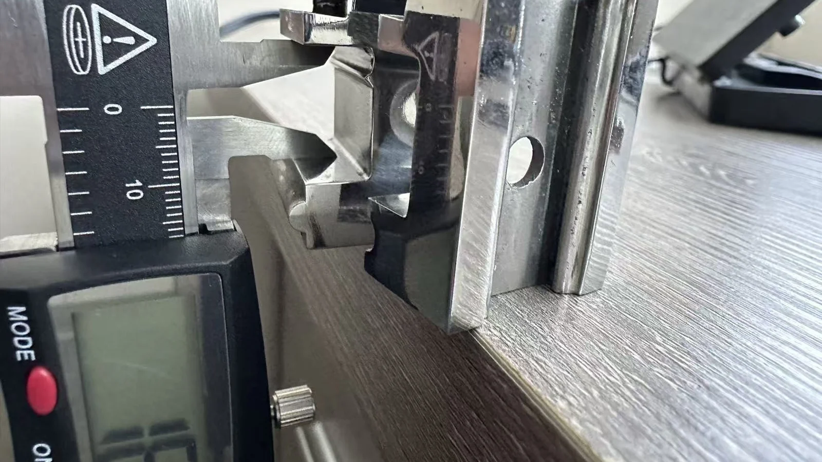
A 3D printed inspection gauge is one of the quieter arguments for metal additive manufacturing: not a flight part, not a demonstrator, but a tool a quality department picks up dozens of times a day. Yuji America Corp. needed three of them for an aerospace project, identical to each other, on a schedule conventional manufacturing could not meet. This is how the part went from a 3D model to three matched SS316L gauges in a live QC process.
Yuji America Corp. develops advanced LED lighting and custom engineering solutions for applications requiring high levels of optical and manufacturing consistency. The end application here stays confidential — what can be said is that it is aerospace, and that the gauge became part of the inspection routine for the project.
A physical check designed for repeated use
A go/no-go gauge answers one question with no interpretation: does this feature fall inside the allowed limits or not. It is the fastest form of dimensional inspection there is, because the tool carries the tolerance in its own geometry. Yuji needed a custom gauge as an additional inspection step, providing a fast, repeatable physical check of critical geometry as part of the QC process.
That places three requirements on the tool: accuracy, repeatability, and durability. A gauge is handled constantly, and contact and friction are part of its working life, so its geometry has to hold over time. A printed polymer part could prove the concept, but it could not be the tool — which made the material choice the decisive part of the project rather than an afterthought.
From model to prototype, before committing to metal
Yuji supplied a 3D model, and we returned a polymer prototype quickly, so the concept could be evaluated in hand before anyone committed to a metal build. That stage earned its place. Working with our applications engineers, Yuji identified several issues in the original design and received specific recommendations on adapting the geometry for manufacture and for daily handling.
One example was increasing material thickness in certain areas so that, after post-processing, the critical geometry would still remain within the specified tolerance. It is an ordinary piece of design-for-additive reasoning, and it is exactly the kind of thing that is cheap to fix in a polymer prototype and expensive to discover in a finished metal tool.
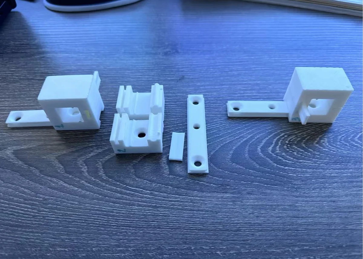
The model was revised and the design went through roughly four rounds — the first polymer prototype, a polished version, one further iteration, and the final design.
Why additive was the practical route
Yuji evaluated conventional manufacturing in parallel, including machining and casting. By their account, the combination of part geometry, project schedule, required quantity, and budget ruled most of those routes out: suppliers either declined the job or could not meet the date.
Three gauges is an awkward quantity. It is too many to treat as a one-off and far too few to absorb tooling costs, and the internal form of a gauge — the profile that does the actual checking — is the kind of geometry that adds machining setups rather than removing them. Metal additive manufacturing was the option that fit all four constraints at once, and our metal 3D printing service took the revised model straight to a build.
| What the tool had to do | How the project met it |
|---|---|
| Check critical geometry directly, by hand | Custom go/no-go gauge, geometry refined across four design rounds |
| Survive repeated handling, contact, and friction | Printed in SS316L stainless steel rather than polymer |
| Read the same in three different pairs of hands | Three parts produced together to the same dimensional accuracy |
| Hold the customer tolerance after post-processing | Material thickness increased in selected areas at the design stage |
| Arrive inside an aerospace project schedule | About two months from initial 3D model to three finished gauges |
Three parts, one inspection standard
This was not a single prototype. Yuji required three identical gauges, because three different people in the QC process would be using them. That reframes the tolerance conversation entirely.
A gauge does not report a measurement — it delivers a verdict. So a deviation between the three tools is not a cosmetic difference: any meaningful variation between the gauges could potentially introduce inconsistency into the inspection process itself. The tool that exists to remove variation would be adding some of its own, and it would do so invisibly, because nothing in the QC record would show which of the three gauges made the call.
Part-to-part consistency is the specification on a gauge set. A single accurate gauge is a measurement tool; three matching gauges are an inspection standard.
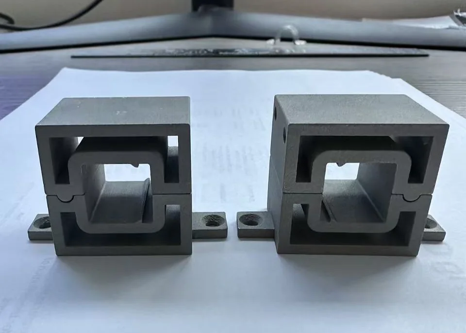
All three parts were produced to the dimensional accuracy and part-to-part consistency the application required, within the tolerance specified by the customer. Printing them in the same material, to the same geometry, in the same production run is what makes that claim reasonable — the three tools share a process history, not just a drawing.
Finishing, evaluated and then ruled out
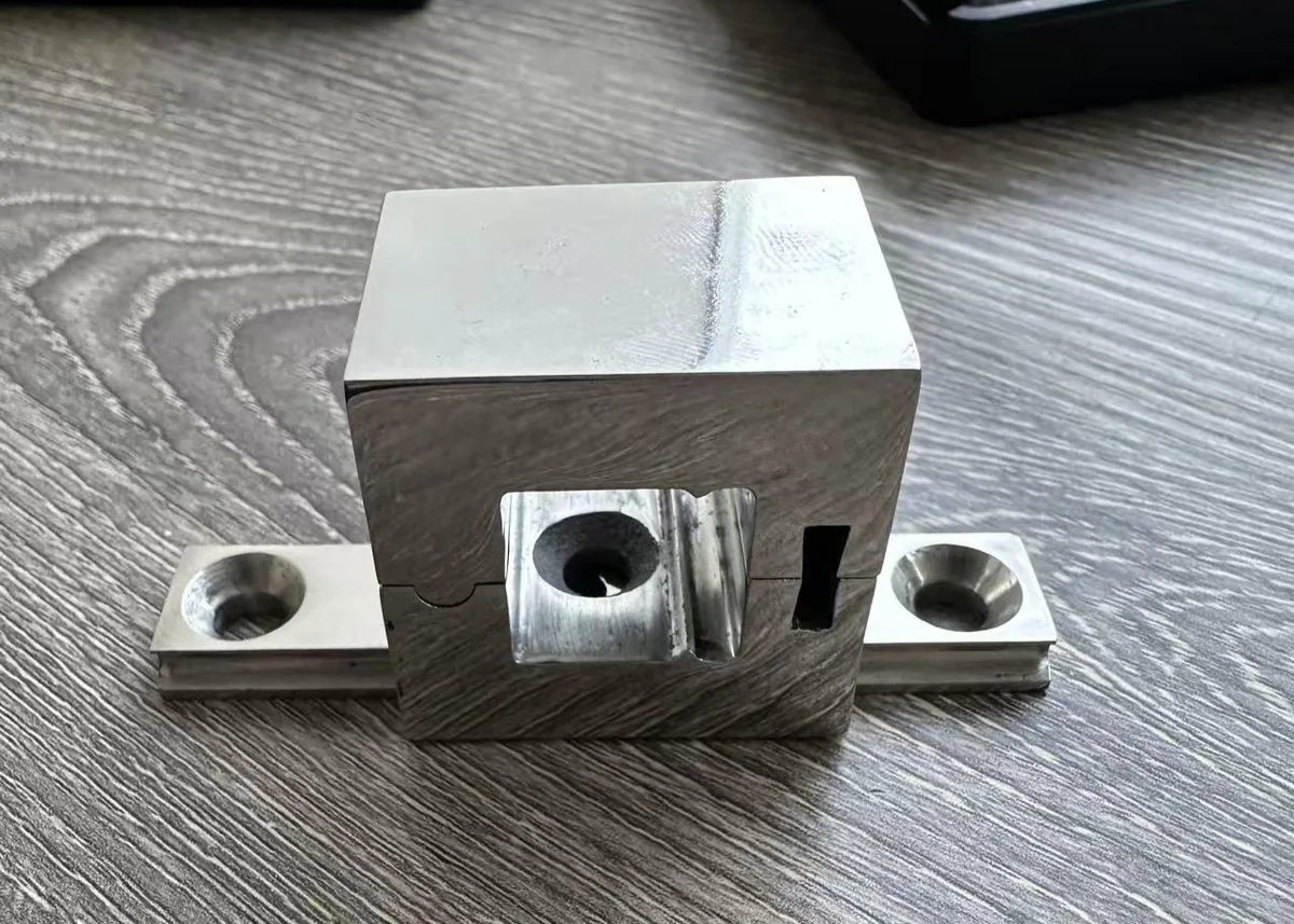
Finishing options were evaluated as part of development. A polished version was produced and tested, but the final configuration did not require polishing — which removed a process step, and with it a source of variation between the three parts. Every hand-guided finishing operation is an opportunity for three nominally identical tools to stop being identical, so leaving it out was a gain rather than a compromise.
Dimensions were verified against the tolerance specified by the customer. A physical gauge and dimensional inspection software answer different questions — the gauge gives a pass or fail in seconds at the bench, while scanning and GD&T reporting tell you by how much and where. On this project the gauge was the fast check, and conventional metrology qualified the gauge itself.
In the QC process
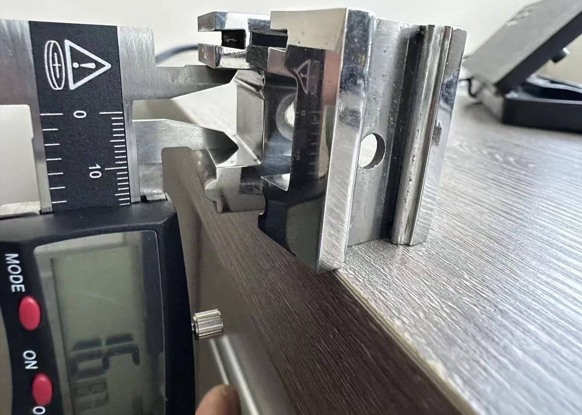
The three gauges were accepted and integrated into the QC process for the project, about two months after the initial 3D model was handed over. That figure covers the whole path — the first polymer prototype, the design review, four rounds of revision, the metal build, and verification — not just print time.
Their engineers gave us feedback at the design stage, flagged manufacturing issues early, and proposed changes that improved the final tool. That understanding of additive manufacturing cut our development time, helped us avoid unnecessary iterations, and kept the overall project cost under control.
This was a highly accuracy-sensitive application. Additive Plus helped us move from an initial concept to a repeatable metal inspection tool that met the precision requirements of an aerospace QC process within a very demanding timeline.
Timur Akhmetshin — LED Division Head, Yuji America Corp.
Where a 3D printed inspection gauge earns its place
Gauges, fixtures, and check tools sit in a bracket that suits additive manufacturing well: low quantities, geometry driven by the part being inspected rather than by ease of machining, and a schedule tied to a production program that has already started. The economics that make additive hard to justify at ten thousand parts are the same economics that make it straightforward at three.
The other half is the design review. The original model was manufacturable, but it needed adjustment to stay inside tolerance after post-processing — the sort of change that costs a revision when it is caught in a polymer prototype and costs a rebuild when it is not. Sending a model out to be printed and having a design conversation before printing are different services, and on an accuracy-sensitive tool the difference shows up in the schedule.
If you have an inspection tool, fixture, or gauge that conventional shops are quoting long, send us the model. See our metal 3D printing services, SS316L stainless steel powder, and solutions for aerospace.
Frequently asked questions
Can a go/no-go gauge be 3D printed in metal?
Yes — a go/no-go gauge can be printed in metal and used as a working inspection tool, provided the design accounts for post-processing. In this project three gauges were printed in SS316L stainless steel and accepted into an aerospace QC process, after the geometry was revised to add material in selected areas so critical dimensions stayed within tolerance once post-processing was done.
Why do inspection gauges have to be identical to each other?
Because a gauge delivers a verdict rather than a measurement, any meaningful variation between gauges shifts the inspection standard itself. When several inspectors each use their own copy, a difference between the tools introduces inconsistency that the QC record cannot trace, since nothing shows which gauge made the call.
What material suits a 3D printed inspection gauge?
SS316L stainless steel is a practical choice for gauges that are handled repeatedly, because it holds its geometry under contact and friction where a printed polymer part would wear. A polymer prototype is still worth printing first to validate fit and handling before committing to a metal build.
How long does a custom metal inspection gauge take?
This project ran about two months from the initial 3D model to three finished gauges. That covers the full path — polymer prototype, design review, roughly four rounds of revision, the metal build, and dimensional verification — not print time alone.
Have a question or a project? Let’s talk.
Tell us what you need — a real applications engineer replies within 24 hours. NDA on request, no sales script.