
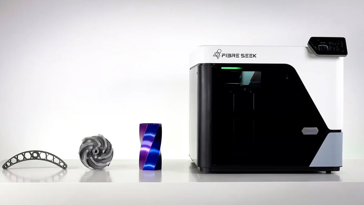
Continuous fiber 3D printing lays unbroken strands of carbon or glass fibre along the load path of a printed part, instead of mixing short fibres into the plastic and hoping for the best. The difference is not incremental. A chopped-fibre bracket is a stiffer plastic bracket. A continuous-fibre bracket is a composite laminate that happens to have been built layer by layer, and it can carry loads that previously required machined aluminium. This guide covers how the process works, what the headline strength numbers actually mean, the design rules the fibre imposes, and where the technology earns its place on a shop floor.
Chopped fibre reinforces the plastic. Continuous fibre replaces it.
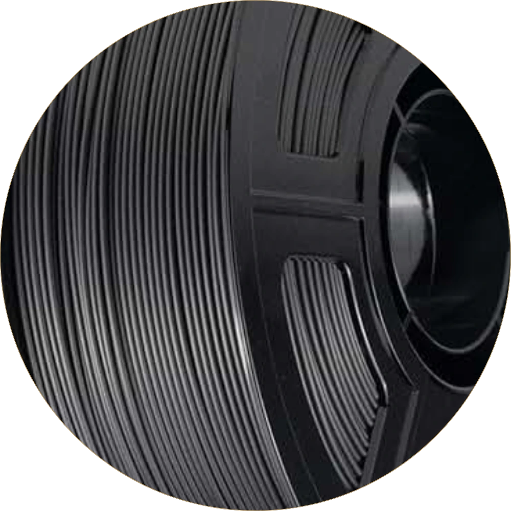
Chopped carbon-fibre filament carries 10–20% short fibres by weight. Those fibres raise the modulus and cut thermal expansion, so parts warp less and flex less — but each fibre is a few hundred microns long, so load transfers through the polymer, not the fibre. Tensile strength stays in the range of the base plastic, typically under 70 MPa. That is covered in detail in our guide to carbon fiber filament grades.
Continuous fibre works the other way round. The strand runs the length of the part, so the polymer only has to transfer shear into the fibre; the fibre carries the tension. Measured on co-extruded specimens, a continuous-carbon/PETG composite at roughly 30 vol% dry fibre reaches about 860 MPa in the fibre direction. That is the same order of magnitude as the ultimate tensile strength of 6061-T6 aluminium, at roughly half the density.
How composite fibre co-extrusion (CFC) works
Most desktop continuous-fibre machines use one of two architectures. The first uses a second, dedicated print head that lays a pre-impregnated fibre tow into channels the plastic head has already printed. The second — composite fibre co-extrusion, or CFC — joins fibre and polymer inside a single nozzle, so both leave the machine as one bead.
CFC is the process behind both machines in our catalogue, and the mechanics are worth being precise about:
- The fibre arrives pre-impregnated and already cured. The tow is infused with a low-viscosity epoxy thermoset and heat-cured into a stiff, filament-like strand roughly 0.35 mm across, holding around 60 vol% fibre.
- The result is a bi-matrix composite. The cured thermoset holds the fibres together and transfers load between them; the extruded thermoplastic binds each bead to its neighbours and forms the rest of the part. Two matrices, two jobs.
- Fibre content is a print setting, not a material choice. Because the polymer feed is independent of the fibre feed, the ratio changes with CFC layer height. Real parts land between roughly 18 and 35 vol% dry fibre — you dial reinforcement up where the load path needs it and back down where it does not.
- The fibre has to be cut. Any continuous strand must be severed at the end of each path, so the head carries a cutter. Cut points are where a fibre path starts and stops, and they are a design consideration, not just a machine detail.
Because the thermoplastic is a separate feed, CFC is not tied to one matrix polymer. PETG, PC, PA and PLA all work, and the base polymer sets the part’s temperature ceiling and toughness exactly as it would in ordinary FFF printing.
What “900 MPa” actually means
Every continuous-fibre machine is marketed with a peak tensile figure, and every one of those figures is a longitudinal number: a test coupon pulled along the fibre, at the machine’s highest fibre fraction. It is a real number. It is also the single most favourable number the material can produce.
| Direction of load | What carries it | Relative strength |
|---|---|---|
| Along the fibre (0°) | The carbon fibre | The headline figure — 860–900 MPa class |
| Across the fibre, in plane (90°) | The polymer matrix only | A fraction of it — matrix-limited |
| Between layers (Z, interlaminar) | Layer-to-layer weld | Weakest — and continuous fibre makes it worse |
That last row is the one engineers underestimate. Interlayer bonding is already the weak axis in any extrusion process, and continuous fibre reduces it further: fibre sitting between adjacent layers displaces the polymer that would otherwise weld them, and the deposited layer below has cooled before the next bead arrives. A continuous-fibre part is a strongly anisotropic laminate. Designing one as if it were an isotropic aluminium billet is the fastest way to break it.
Where the fibre has to go — design rules
Continuous fibre imposes constraints an unreinforced print does not. Four of them decide whether a part works:
- Orient the part so the load path is in-plane. Fibre can only be laid within a layer, never up the Z axis. A part loaded through its build direction gets no fibre benefit at all — reorient it, or split and bond it.
- Respect the minimum bend radius. A cured tow will not turn a sharp corner. Path planners insert curved transitions to hold a minimum curvature radius, and sharper corner angles demand larger radii. Force a tight corner and the fibre dislocates, leaving a polymer-only node exactly where the geometry concentrates stress.
- Reinforce walls and ribs, not solid volume. Fibre in the outer contours resists bending far more efficiently than fibre buried in the neutral axis. Continuous fibre in a well-placed shell and a lattice core beats a solid block of it on both weight and cost.
- Plan the cut points. Every fibre path terminates somewhere, and a termination is a discontinuity. Put them away from peak stress, and prefer closed loops around holes and bosses over short stubs.
None of this needs composites experience in the classical sense — the slicers ship with fibre-routing presets — but it does need the part to be designed with the fibre in mind rather than reinforced after the fact.
When it beats machined aluminium
The honest comparison is not “printed part vs milled part” in the abstract; it is a specific bracket, in a specific quantity, on a specific deadline.
| Continuous-fibre print | Machined 6061-T6 | |
|---|---|---|
| Tensile strength | ~860–900 MPa along the fibre; matrix-limited off-axis | ~310 MPa, in every direction |
| Density | ~1.4 g/cm³ | 2.70 g/cm³ |
| Behaviour | Anisotropic — strength follows the fibre | Isotropic — predictable in any orientation |
| Setup | None — file to part overnight | Fixturing, tooling, programming |
| Best at | One-offs and low volume, complex geometry, weight-critical parts | Volume, tight tolerances, loads in every direction |
Continuous fibre wins where the load path is known and directional, the quantity is small, and mass matters: UAV frames and arms, robot end-effectors, load-bearing brackets, and stiff shop-floor jigs, fixtures and composite tooling. Aluminium keeps the work where tolerances are tight, loads are multiaxial, or the quantity justifies a fixture.
The machines that do it
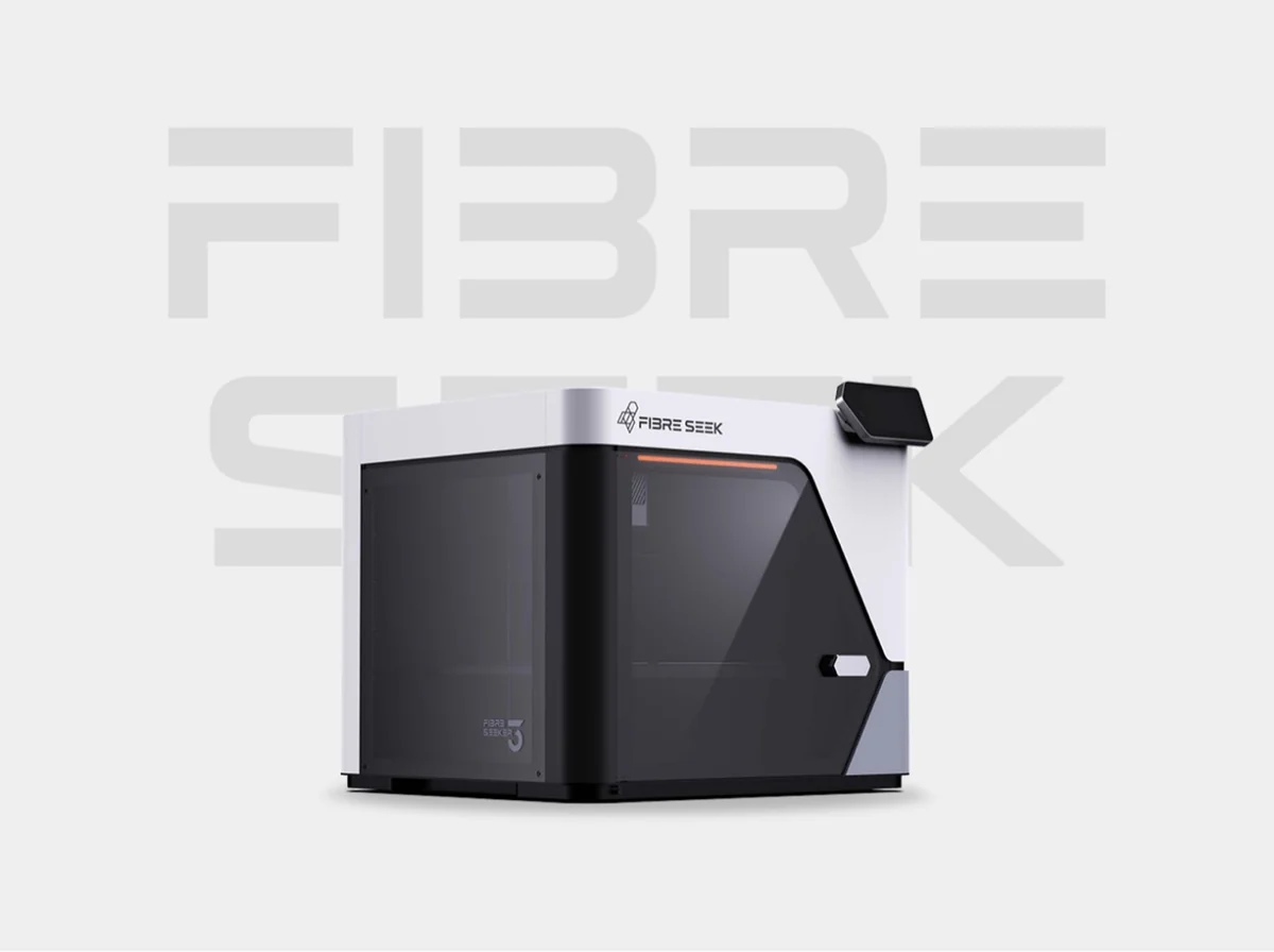
Until recently, continuous fibre meant an industrial machine. That changed with the FibreSeeker 3, a desktop CFC system that raised roughly $4.7 million from 1,539 backers on Kickstarter and moved into production and shipping during 2026. It runs a 0.4 mm FFF nozzle and a 0.7 mm CFC nozzle with an integrated fibre cutter, both to 350 °C, over a 300 × 300 × 245 mm build volume, with a 65 °C chamber and a 110 °C bed. Three modes cover the workflow: plastic only at up to 500 mm/s for iteration, fibre plus plastic for reinforced parts, and a fibre-dominant lay-up for peak load. Continuous-fibre throughput runs to 20 cc/h — fibre printing is a deliberate, slower operation than plastic printing, and planning around that matters more than the top speed does. It starts at $2,999. The company behind it, FibreSeek, was formed by the core team behind Anisoprint, which is where the CFC process originated (3Dnatives).
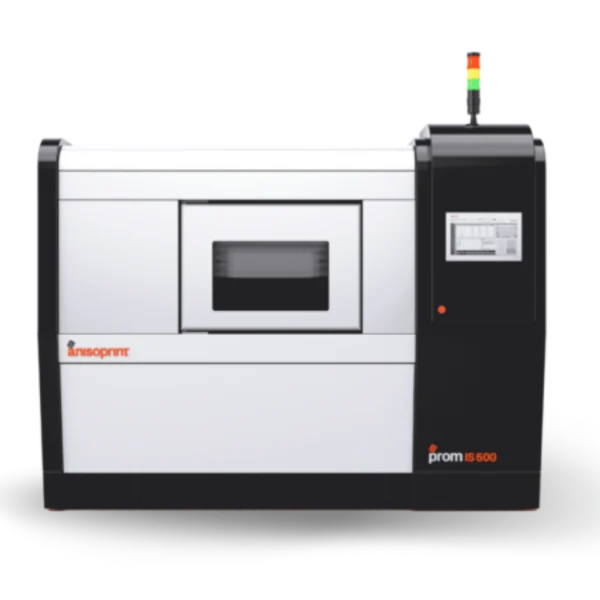
For production-scale parts, the Anisoprint PROM IS 500 runs the same co-extrusion principle in a 600 × 420 × 300 mm envelope with the thermal control that high-temperature matrix polymers need. The choice between them is rarely about the fibre — it is about part size, matrix polymer, and how many parts a week the machine has to produce.
Deciding whether it fits your parts
Start with a part that is currently machined from aluminium, loaded in a known direction, needed in single digits, and where weight costs you something. That is where continuous fibre pays for itself first. Parts loaded in every direction, parts needing tight tolerances straight off the machine, and parts you make a thousand of are still machining and moulding work. If reinforcement is about rigidity rather than load capacity, chopped carbon-fibre filament on a standard FFF machine is the cheaper answer — and our overview of composite 3D printing sets out where each approach belongs.
Send us the part and the load case and we will tell you whether the fibre can be routed where it needs to go, and which machine fits: the FibreSeeker 3 for desktop work, the Anisoprint PROM IS 500 for production volume, or the wider FFF and composite printer range.
Frequently asked questions
What is continuous fiber 3D printing?
Continuous fiber 3D printing lays an unbroken strand of carbon or glass fibre along the load path of a part while the printer extrudes the surrounding thermoplastic. Unlike chopped carbon-fibre filament, which contains short fibres a few hundred microns long, the continuous strand carries tensile load directly, producing a printed composite laminate rather than a stiffened plastic part.
How strong are continuous fiber 3D printed parts?
Along the fibre direction, co-extruded continuous-carbon composites reach roughly 860 to 900 MPa at about 30 vol% dry fibre - the same order as the ultimate tensile strength of 6061-T6 aluminium at roughly half the density. Across the fibre and between layers the part is matrix-limited and much weaker, so the headline figure applies only to loads you can route a fibre along.
What is the difference between continuous fiber and carbon fiber filament?
Carbon fibre filament is a thermoplastic loaded with 10 to 20 percent chopped fibres by weight; it raises stiffness and dimensional stability but leaves tensile strength near that of the base plastic, typically under 70 MPa. Continuous fibre is a single unbroken tow routed through the part, so the fibre itself carries load and strength rises by an order of magnitude in that direction.
Which 3D printers can print continuous carbon fiber?
Additive Plus supplies two composite fibre co-extrusion (CFC) machines: the FibreSeeker 3, a desktop system with a 0.4 mm FFF and a 0.7 mm CFC nozzle over a 300 x 300 x 245 mm build volume from $2,999, and the industrial Anisoprint PROM IS 500 with a 600 x 420 x 300 mm envelope for production volumes.
Have a question or a project? Let’s talk.
Tell us what you need — a real applications engineer replies within 24 hours. NDA on request, no sales script.