
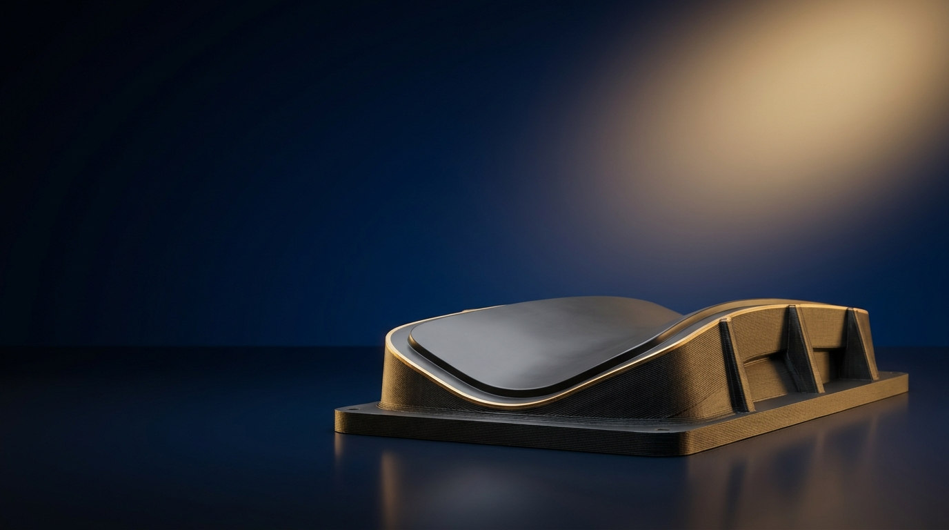
Large-format additive manufacturing (LFAM) — large format 3D printing at industrial scale — is what you reach for when the part is too big for a desktop machine and too slow or costly to build any other way — a two-metre autoclave mould, a full-scale layup tool, a structural bracket the size of a car door. Instead of milling it from a billet or laminating it by hand over weeks, a large-format printer lays it down near net shape in hours, then a single CNC pass brings the working face to tolerance. This guide goes past the marketing into how the processes actually behave, the engineering limits you have to design around, and how to choose a system.
What counts as large format
There is no hard cutoff, but the label applies once the build envelope passes roughly half a metre in an axis and runs into several metres at the top end. At that scale the economics invert: the part is no longer a cheap prototype but a tool or structure where every day of lead time and every kilogram of stock carries real cost. That is precisely where additive pulls ahead of subtractive and hand layup.
The process families — and how they actually behave
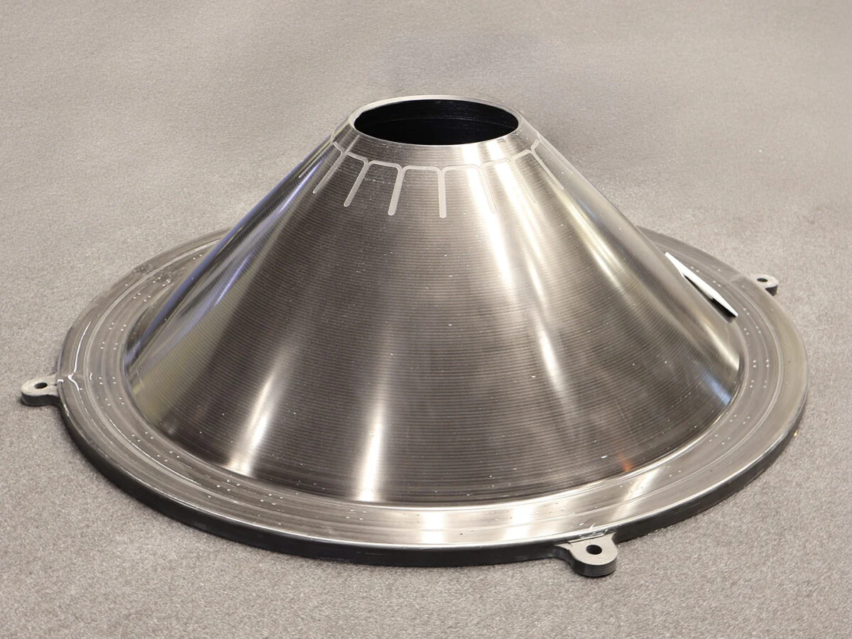
Four approaches cover large-scale work. The number that separates them is deposition rate against resolution — you trade one for the other, and then machine back the difference.
| Process | Layer height | Bead width | Deposition rate | Best for |
|---|---|---|---|---|
| Large-format FFF (filament) | 0.15–0.4 mm | 0.3–1.0 mm | low | Higher-detail functional parts, jigs, fixtures |
| LFAM / FGF (pellet) | 1–5 mm | 3–10 mm | ~2–18 kg/h typical, up to 75–227 kg/h on the largest systems | Moulds, layup tools, large structures |
| Industrial SLA | 0.05–0.15 mm | — | low, high detail | Large master patterns, smooth-surface parts |
| Metal WAAM / DED | coarse | wide | high | Large near-net metal parts and tooling |
Pellet FGF numbers are worth internalising: bead width and layer height are five to ten times a desktop machine’s, which is why an industrial pellet system prints an ABS part at roughly 2–15 kg/h and the largest gantry systems reach hundreds of kilograms per hour. A robotic platform such as the Caracol Heron AM is quoted by its maker at 2 to 75 kg/h, process temperatures up to 450 °C, on a six-axis arm reaching up to 3.9 m. Resolution is coarse by design — you get the geometry fast, then finish it.
Why pellets, not filament
At scale, feedstock format decides the budget. Pellets run roughly 40–60% cheaper per kilogram than filament, and a pellet extruder can push material at up to about 80 times the rate of a filament head. On a tool that weighs 100 kg, that is the difference between a print measured in hours and one measured in days — and a material bill measured in hundreds rather than thousands. It is the single biggest reason LFAM tooling has moved from novelty to production.
The hard part: Z-axis anisotropy
Interlayer bonding is a thermal process: the previous bead must still be hot enough for polymer chains to diffuse across the interface when the next bead lands. If it has cooled below its glass transition first, the chains cannot entangle and the bond is brittle. The gap is real and measurable. Published datasheets for carbon-filled LFAM resins show tensile strength in the print plane roughly double that across the layers — a modified polycarbonate grade measures about 112 MPa in X versus 50 MPa in Z (Z is only ~45% of X), and a high-temperature PEI-type grade about 126 MPa in X versus 68 MPa in Z.
Three levers close the gap: a heated build chamber and controlled layer time so each bead stays above its transition until the next arrives; bead-geometry tuning for contact area; and, at the leading edge, active interlayer heating — a focused-LED system that re-melts a thin layer at the deposition interface. On an aerospace PAEK, that approach reportedly lifted cross-layer strength to roughly 92 MPa in Z against 96 MPa in-plane — effectively isotropic, on parts that previously could not be finished without delaminating. Carbon fibre is the default reinforcement here not only for stiffness but because it lowers warpage versus glass.
Print near net, then machine: the hybrid workflow
No large extrusion print is a finished part off the bed. The production model is near-net-shape print → single CNC operation → use. LFAM lays down the bulk fast and cheap; CNC removes a few millimetres of stock to bring the working surface to tolerance and finish. Machined composite tooling faces reach roughly 0.8 µm (Ra 32 µin) or better. On gantry LFAM systems the print head and spindle share the same machine, so print and trim happen without a re-fixture.
Printed autoclave tooling: the numbers that matter
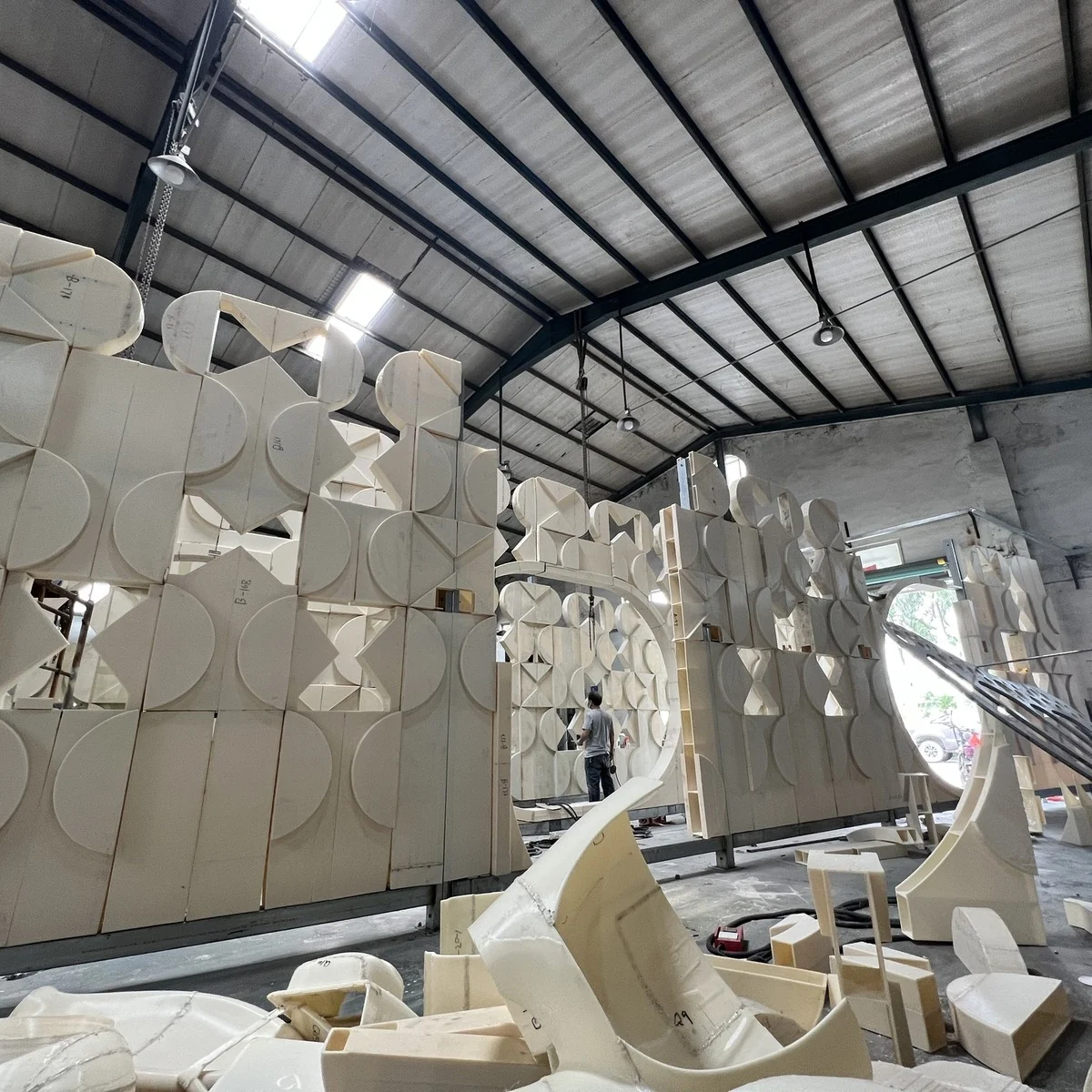
The demanding test for a printed mould is surviving repeated autoclave cures. It holds up. In an independent evaluation, an Ultem-based printed tool ran 20 autoclave cycles at 177 °C and 85–90 psi, and 99.7% of the tool surface stayed within ±0.004 in of baseline — inside the ±0.005 in aerospace band — with a sprayed sealing coat keeping the face vacuum-tight. Tooling-resin suppliers report their materials surviving more than 500 autoclave cycles without meaningful degradation. That is why LFAM has displaced machined and laid-up masters for short-run composite tools.
Materials: match the grade to the cure temperature
Reinforced thermoplastic choice follows the service temperature the tool or part must hold.
| Material | Service temp / HDT | Strength (X) | Use |
|---|---|---|---|
| ABS + 20% carbon fibre | low | ~75 MPa | General large prints, jigs, fixtures — the workhorse |
| PP + 30% glass fibre | low | ~85 MPa | Chemical-resistant tanks, marine, ducting |
| Modified PC + 20% CF | service ~121 °C, HDT ~144 °C | ~112 MPa | Room- to medium-temperature tooling, master moulds |
| PEI/Ultem-type + 20% CF | service ~176 °C, HDT ~212 °C | ~126 MPa | High-temperature autoclave tooling |
Service temperatures come from the resin datasheets linked above; treat them as the design ceiling, not a target.
What it delivers: real cases
The gains are consistent and quantified across independent and vendor reports:
- Aerospace composite tool — 2,200 × 2,200 × 600 mm, 180 kg, polycarbonate + 20% carbon fibre, printed in about 19 hours, then CNC-machined and autoclave-processed. Reported lead time −50%, cost −30%, waste −50%, weight −50% versus conventional tooling.
- Marine stern structure — 780 × 270 × 610 mm, 9.5 kg, ASA + 20% glass fibre, printed in 14 hours. The manufacturer reports lead time −60%, cost −60%, waste −30% by printing near net and skipping the plug-and-mould step.
Metal at large format: WAAM
For large metal parts, wire-arc additive (WAAM/DED) melts a metal wire with an electric arc to build near-net shapes in titanium, steel, aluminium and nickel alloys, then machines to tolerance. On expensive metals the material case is decisive: makers report titanium waste cut by up to 90% and custom-part lead times falling from around two years to about one month. It is the same near-net logic as polymer LFAM, applied where the billet itself is the cost.
Large-format SLA for master patterns
Where the deliverable is a smooth, detailed master rather than a structural tool, large-format stereolithography fits. Industrial SLA systems reach build volumes into the metre-plus range and hold roughly ±0.1 mm, with castable resins that let a foundry go from CAD to an investment-casting master in a day or two. See our industrial SLA systems for that route.
Choosing a large format 3D printing system
Work in this order:
- Size to the real part. Take the biggest part you actually build, add clearance, and stop — oversizing the envelope wastes floor space and money.
- Match the material to the cure temperature. Reinforced pellets for stiff tooling, high-temp PEI grades for autoclave work, engineering filament for functional parts, resin for smooth masters.
- Prioritise deposition rate over resolution. Most large parts are CNC-finished anyway, so throughput and thermal control matter more than layer detail.
- Plan the finishing. Budget the CNC pass and, for tooling, the sealing coat from the start — they are part of the process, not an afterthought.
Browse systems by build size and process in our large-format 3D printer category, or tell us the part and the cure temperature and we will narrow it down.
Related guides: Additive manufacturing in aerospace · Inconel 3D printing
Related: Large-format (FGF) 3D printing service · Large-format printers
Frequently asked questions
What is large format 3D printing?
Building parts too big for a desktop machine, roughly half a metre and up, layer by layer. It is usually done by pellet extrusion (LFAM), large-format filament, or industrial SLA.
What can large format 3D printing make?
Composite layup tools and moulds, large master patterns for casting, big functional brackets and ducting, and architectural or design pieces.
Is large format 3D printing cheaper than machining?
Often, for complex or one-off parts. Near-net-shape printing removes most of the waste a mill would cut, and pellet feedstock is inexpensive; parts are typically CNC-finished afterward.
What materials are used in large format 3D printing?
Reinforced thermoplastic pellets such as carbon- or glass-filled ABS, PC and PP, engineering filaments, and photopolymer or castable resin for industrial SLA.
Have a question or a project? Let’s talk.
Tell us what you need — a real applications engineer replies within 24 hours. NDA on request, no sales script.